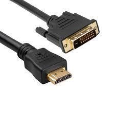
DVI Cable
DVI (Digital Visual Interface) cables implement the DVI video interface standard in order to enable high visual quality displays on LCD flat panel and digital projector displays. The Digital Display Working Group (DDWG) created this standard as a succeeding technology to the traditional VGA connection standard. DVI connector technology carries uncompressed digital video and is partially compatible with the High-Definition Multimedia Interface (HDMI) standard in the DVI-D (Digital) mode and with VGA when operating in analog mode (DVI-A).
How does DVI Work?
The DVI interface uses a digital protocol that transmits illuminated pixels as binary data. The information can be displayed in raw form that will interpret the transmitted number and apply the associated brightness to the appropriate pixel on the display screen. Each pixel in the device’s output buffer that transmits over a DVI cable corresponds to a pixel on the display device. As a result, the DVI standard improves the display’s visual quality by avoiding the issues found in VGA connections that are impacted by electrical noise and other forms of analog distortion.
DVI Connectors
DVI connectors use pins to send DVI-native digital video signals to display devices. If there is a dual link system, additional pins are used to make use of the second set of data signals. DVI connectors also support the traditional VGA data set so that traditional monitors can be connected via a basic plug adapter in order to make the DVI connector a universal standard. The letter that follows the DVI label indicates the type of connection it is, for example, DVI-D (digital connections), DVI-A (Analog connections), DVI-I (Integrate digital and analog connections).
DVI Specification
The minimum clock frequency that he DVI specification supports is 25.175 MHz. The single link maximum data rate is 4.9 Gbit/s at 165 MHz, with a 8b/10b overhead. If the overhead is removed, the data rate reduces to 3.96 Gbit/s. The standard requires a minimum of 24 bits per pixel support in all supported resolutions, less than 24 bits per pixel is optional. Display modes implementing the DVI standard are capable of displays that are up to 3,840 pixels in width and 2,400 in height, depending on the click rate and if implementing a single or dual link.
DVI Pinouts
The pinouts for DVI connectors are:
Pin 1 – TMDS data 2(-) – Digital Red (link 1)
Pin 2 – TMDS data 2(+) – Digital Red (link 1)
Pin 3 – TMDS data 2/4 shield
Pin 4 – TMDS data 4 (-) – Digital Green (link 2)
Pin 5 – TMDS data 4 (+) – Digital Green (link 2)
Pin 6 – DDC Clock
Pin 7 – DDC Data
Pin 8 – Analog Vertical Synchronization
Pin 9 – TMDS Data 1 (-) Digital Green (-) (link 1)
Pin 10 – TMDS Data 1 (+) Digital Green (+) (link 1)
Pin 11 – TMDS Data 1/3 Shield
Pin 12 – TMDS Data 3 (-) Digital Blue (-) (link 2)
Pin 13 – TMDS Data 3 (+) Digital Blue (+) (link 2)
Pin 14 – +5 V – Power for monitor when in standby
Pin 15 – Ground – Return for pin 14 and an analog synchronization
Pin 16 – Hot Plug Detect
Pin 17 – TMDS Data 0 (-) Digital blue (-) (link 1) and digital synchronization
Pin 18 – TMDS Data 0(+) Digital blue (+) (link 1) and digital synchronization
Pin 19 – TMDS Data 0/5 shield
Pin 20 – TMDS Data 5 (-) – Digital red (-) (link 2)
Pin 21 – TMDS Data 5 (+) Digital Red (+) (link 2)
Pin 22 – TMDS clock shield
Pin 23 – TMDS clock (+) Digital Clock + (links 1 and 2)
Pin 24 – TMDS Clock (-) Digital Clock (-) (links 1 and 2)
C1 – Analog red
C2 – Analog green
C3 – Analog blue
C4 – Analog horizontal synchronization
C5 – Analog ground (return for R, G, and B signals)


Comments - 2 Responses to “DVI Cable”
Sorry but comments are closed at this time.